English

Comprehensive guide to using InvisBrace

INVISBRACE 0.5.0

Detailed instructions for using InvisBrace

Create digital orthodontic treatment plans for lingual braces, individual bases, and indirect attachments and export production data.

Full 20 sections of PDF20 photos taken directly from the applicationOctober 12, 2026

About this document

The document describes the entire visible workflow of InvisBrace Lingual 0.5.0. Screenshot taken directly from a Qt/VTK application running in English mode. Clinical 3D example using a working copy of the case Sample Patient_0000 provided by the user, including individual braces for all planned teeth. The original ZIP is not changed.

Warning: InvisBrace is a clinical support CAD tool. The treating physician remains responsible for diagnosis, treatment planning, appliance ordering, mesh testing, manufacturing setup, and final approval.

Convention

Control name in boldThe label is as shown in the application.
Number of FDI teethTwo-digit notation: the first digit is the fourth; The following number is the tooth position from the midline.
Original / setupOriginal is the imported clinical geometry; setup is the planned tooth position.
Blue selection statusActive switch, mode, tooth or tool.
Gray off statusThe functionality is not available until the prerequisites are completed.

Table of contents — 20 sections

1. Process overview

A case goes from patient records and scan data preparation, through segmentation, setup, bracket positioning, individual base design and finally production data export. Tabs are numbered intentionally; The following tab depends on the data created in the previous tab.

1. PatientsEnter identification, clinical characteristics, missing/extracted teeth, treatment goals, case access and bracket library.
2. Import ScansImport, orient, crop, and manually align the upper and lower jaw meshes.
3. Dental segmentationSeparate the teeth from the gums, determine the tooth axis and complete each arch.
4A. Ideal occlusal planeSet up the reference coordinate system for the proposed setup.
4B. Tooth setupMove teeth, check contact and fit/adjust ideal arch form.
5A. Archwire planeEstablish the vertical and angular reference for the lingual arch wire.
5B. BracketsSelect the library, create the lingual archwire, place the brackets, and fine-tune the bracket/tooth position.
6. Customized baseDraw a personalized base and prepare a direct printing stick or wax casting stick.
7. ExportCreate models, trays or jigs and export fabrication files as bowstring PDFs.

Recommended completion sequence

  1. Create or open a case, check the patient data row and immediately save to create a case ZIP.
  2. Enter both signs if applicable; Edit, orient and cut until the clinical perspective is correct.
  3. Segment every tooth needed, check the shaft, then use Finish current arch for the upper and lower jaw.
  4. Set the ideal plane before aligning teeth; Check lateral contact and occlusion after setup.
  5. Place the wire plane, select each function library, auto-place and then fine-tune.
  6. Create individual bases as needed and check for correct Original, Direct print or Wax casting tree thread.
  7. In Export, select the output type/position, check the bracket mode for each tooth, create support/seal and export only after visual inspection.
Recommendation: Save after each major milestone. Undo/Redo is useful for the last edit, but the saved ZIP is the permanent restore point.

2. Main window, files and global commands

Menu Language
Menu Language; Items with a check mark are the active language.

Commands above

Undo (Ctrl+Z)Reverse the most recent undoable change.
Redo (Ctrl+Y)Reapply the undone change.
Open (Ctrl+O)Open the ZIP of InvisBrace.
Save (Ctrl+S)Update current shift ZIP.
Save As (Ctrl+Shift+S)Record shifts to new ZIP while keeping shifts.
Quit case (Ctrl+N)Close shift and return to clean workspace; Save before being asked.
Bracket libraryImport/remove libraries or open full manager.
AccountLog in, view your account, change your password, buy credits or log out.
AboutDisplays product, version, and application information.
LanguageSwitch language; Some labels will be rearranged.

Content and handling of ZIP ca

  • Saved ZIP contains clinical state, transform 4×4, GUI state, and internal resources needed to reopen.
  • Definition of braces taken from the installed library. Keep the same library on every open shift workstation.
  • Use Save As before testing that is difficult to reverse or when creating a new version of the plan.
  • Do not rename or delete files in the extracted case; Open and save via InvisBrace.
The status line reporting extended geometry operations. Wait for preparation/generation to complete before evaluating the preview or starting another export.

3. 3D view interaction and common controls

Most tabs include the narrow panel, mid 3D viewport, floating FDI panel, and opacity controls. Axis markers use red for X, green for Y and blue for Z.

Drag the left mouse button in an empty spaceRotate the camera in normal view mode.
RollerZoom; You should zoom slowly when editing edges or selecting small surfaces.
Drag the middle mousePan the camera according to standard VTK interaction.
Left click the objectSelect teeth, brackets, supports, points or surfaces as the tab allows.
Ctrl-clickTurn on/off each tooth when selecting multiple teeth.
Shift-clickExtend selection continuously; Special tools can use Shift for other functions as specified.
Right-clickDelete boundary or support points depending on the context.
Reset viewRestore default camera, leaving mesh coordinates unchanged.
Upper / Lower opacityChange the visibility of each arc while preserving the geometry.
3D gizmoDrag the translation or rotation arrow; Numerical control for precise value.
The selection behavior is tool dependent. Read the instructions in the active tab before clicking the model.

Digital control

  • Use the slider to make rough adjustments, subtract/add for iterations or enter exact values.
  • Press Enter after the typed value when the control requests it.
  • Translation in mm, rotation in degrees; slot can be inches or mm according to metadata.
  • A disabled control means the parent feature is disabled or the prerequisite geometry has not been created.

4. Step 1 —Patients

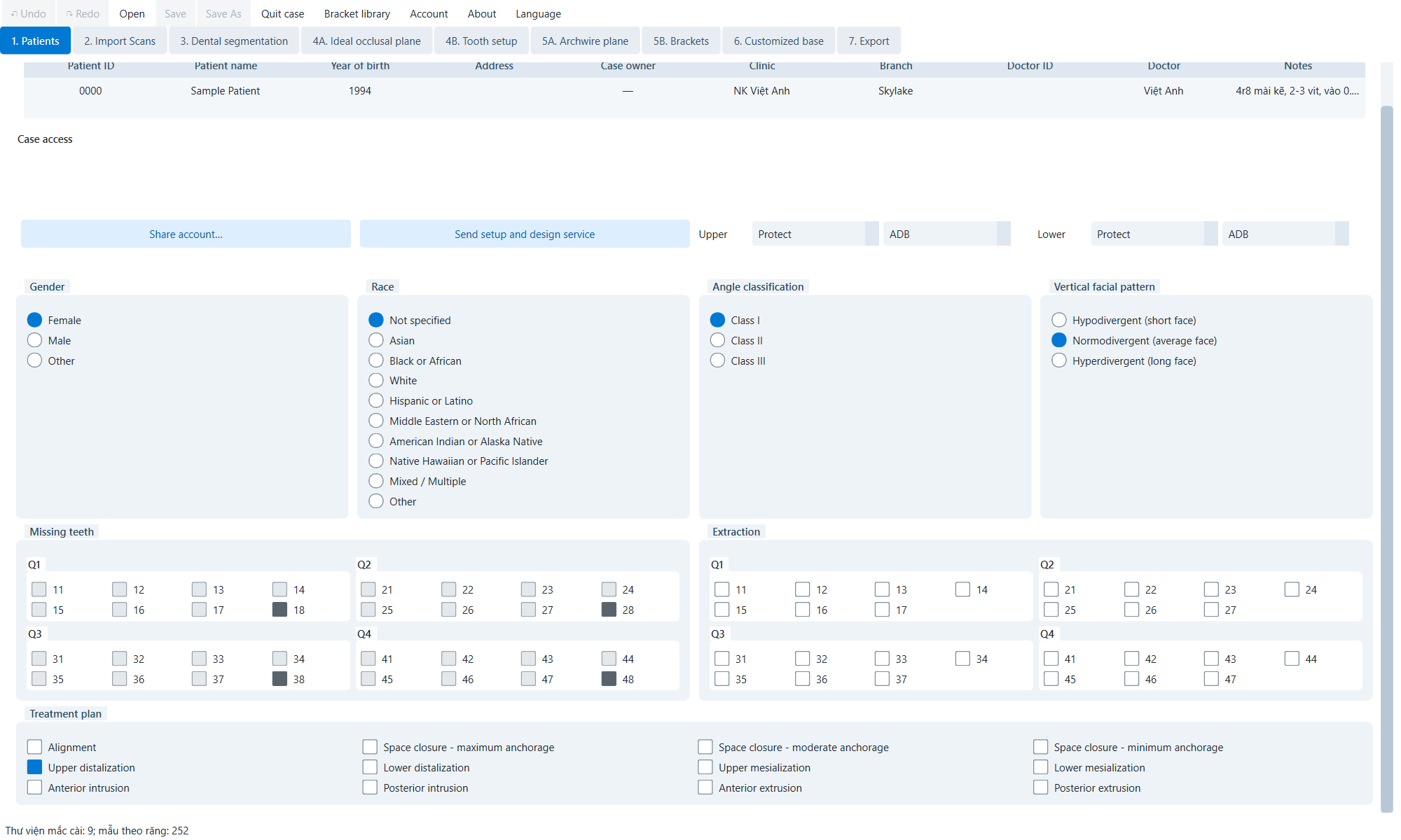
Patients part 1
Identifiers, access, libraries and clinical classification.
Patient details tableEdit Patient ID, Patient name, Year of birth, Address, Case owner, Clinic, Branch, Doctor ID, Doctor and Notes directly in the row.
Share account…Grant permissions to another account; delete existing tag with x button.
Send setup and design serviceSubmit patient/setup brief to design service after checking required fields and goals.
Upper / Lower manufacturerChoose a separate company for each sign.
Upper / Lower libraryChoose a specific library for each sign.
GenderFemale, Male or Other.
RaceSelect demographic groups, including Not specified and Mixed / Multiple.
Angle classificationClass I, II or III.
Vertical facial patternHypodivergent, Normodivergent or Hyperdivergent.
Patients part 2
Lost teeth, extraction plan and treatment options.
Missing teethSelect FDI not in the input tooth set; locked after completing the relevant arc.
Extraction teethSelect the tooth to be extracted; selection is kept if tooth setup is reset.
Treatment planSelect Alignment; close maximum/medium/minimum anchorage intervals; distalization/mesialization of the upper/lower jaw; subsidence/extrusion of anterior/posterior teeth.
Confirm missing teeth and extraction before segmentation. Late changes may invalidate the tooth list and posterior geometry.

5. Step 2 — Import Scans

Import Scans
Mandible entered in live photo.

Import receives mesh STL, PLY and OBJ. Do each arc; Check scale, direction, completeness and topology.

Import upper meshLoad the upper jaw; mesh is copied/edited into the workspace.
Import lower meshLoad mandibular STL, PLY or OBJ.
Upper / LowerSelect the arc being cut or positioned.
Apply trimApply a clipping border and keep the selected side.
Smooth trim moreSmoothen cutting edges.
Invert kept sideChange the holding side.
Show translateShow/hide the jaw translation handle.
Show rotateShow/hide rotating handle; can be shown with translation.
Reset viewRestore camera; mesh coordinates remain unchanged.

Process

  1. Enter arc and check for holes, loose islands, island surfaces or unusual proportions.
  2. Choose a bow; Draw the applicable gingival margin and check the retention side before applying.
  3. For use only Smooth trim more when needed; Excessive can cause loss of anatomy.
  4. If there is no bite scan, use a gizmo to make a reasonable functional correlation.
  5. Reset view and check chewing direction, anterior, lateral before segmentation.
Move the function manually to change the pose mesh; Resetting view only changes the camera.

6. Step 3 — Dental segmentation

Segmentation
Segmental space with tooth axis gizmo.
18 / 28 / 38 / 48Turn on optional wisdom teeth.
Semi-automaticUse the tooth neck point to calculate the margin.
ManualEdit margins manually.
Trim toothApply cervical margins and separate teeth.
Torque (Rx)Rotate around the near-far axis.
Tip (Ry)Rotate around the external-internal axis.
Rotation (Rz)Rotate around vertical axis.
Confirm tooth axesAccepts current axis.
Finish current archCreates the final state of the segment/gum and locks the missing tooth.
Reset segmentationRemove the supply result and restore the source.

Procedure for each tooth

  1. Select FDI arch and teeth.
  2. Select Semi-automatic or Manual; click along the neck of the tooth.
  3. Correct/delete the wrong point then press Trim tooth.
  4. Check from multiple angles; Undo and redraw if side gums/teeth are involved.
  5. Align the axis and press Confirm tooth axes.
  6. Repeat every tooth; only Finish current arch after full inspection.
Finish current arch is a milestone operation. Check the nominal, boundary and front axle.

7. Step 4A — Ideal occlusal plane

Ideal plane
Control and 3D reference plane.
Translate XMove right-left.
Translate YMove front-back.
Translate ZMove vertically.
Rotate X / Y / ZSet the angle around the global axes.
Hide/Show translateTurn on/off forward arrow.
Hide/Show rotateTurn on/off rotation.
Reset viewReset the camera, do not change the plane.

Clinical setting

  1. Show both signs; Reduce opacity and mask mold.
  2. Translate to the expected vertical reference.
  3. Rotate in the direction of the occlusal plane at the anterior and lateral angles.
  4. Check is in the middle, no unintended yaw.
  5. Pre-save tooth setup.
The Ideal plane frame in the following tab is derived from this; The error spreads to the direction of tooth and bracket movement.

8. Step 4B — Tooth setup

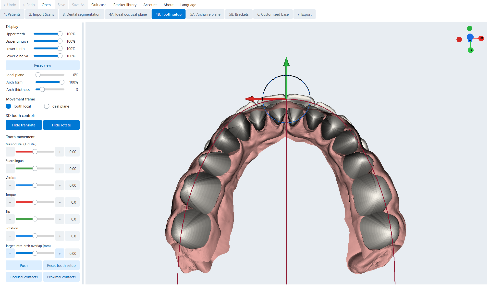
Tooth setup 1
Tooth selection, ideal arc, contact and 3D control.
Tooth localMove in the crown axis system from segmentation.
Ideal planeProject X/Y to the ideal plane, keeping Z perpendicular.
Translate X / Y / ZPrecise translation of teeth or groups.
Torque / Tip / RotationRotate accurately around the clinical axis.
Hide translate / Hide rotateShow/hide gizmo part.
Target intra-arch overlapSet near-far overlap; Positive creates overlap, negative creates space.
PushSolve the central incisors symmetrically and then move them distally sequentially.
Reset tooth setupRestores original position and gums; keep extraction/show state.
Occlusal contactsEnable/disable interarc contact.
Proximal contactsEnable/disable contact in arc.
Tooth setup 2
Arc form, width, apex, rotation and tooth list.
Taper / Ovoid / SquareInitial arc preset.
Arch width WChange arc width, mm.
Apex translate X / YMove apex.
Arch rotate around apexRotate the entire arc around the apex.
Show 3D gizmoShow the bow gizmo.
FDI tooth selectorChoose teeth; Ctrl/Shift for groups where supported.

Test sequence

  1. Select preset and fit width/apex.
  2. Place the central incisors, then move back and maintain symmetry if the indication does not require asymmetry.
  3. Use contact to handle unwanted lateral overlap and joint penetration.
  4. Check chewing direction, front, side; Save revision before Push on heavily edited setup.
The exposure map is a diagnostic overlay, not an automatic approval.

9. Step 5A — Archwire plane

Archwire plane
Plane of the wire on the sample case.
Upper / LowerSelect the active plane.
Translate ZMove vertically.
Rotate XSet pitch.
Rotate YSet roll.
Show 3D gizmoShow/hide gizmo.
Reset viewRestore clinical camera.
  1. Select the arc and make the opposite arc transparent if necessary.
  2. Set the height according to the expected tongue slot position.
  3. Adjust X/Y to get a smooth reference through the tooth set.
  4. Repeat the other arc; Compare symmetry and clearance.
Here is the reference; clearance and collision must still be checked in Step 5B.

10. Step 5B — Brackets

Brackets
Place the bracket on the lower jaw setup with the archwire.
Upper / LowerSelect the bow that needs to be edited, the library, strings and position.
Manufacturer / librarySelect the installed brace system.
Lingual archwire shapeChoose S, M, L or your own library preset.
Front width y=10 mmAdjust the front width of the string.
Posterior flareAdjust the rear opening.
Apex X / Apex YTranslate the apex wire.
Rotate wire ZRotate the rope yaw.
Show 3D gizmoShow string bow gizmo.
Auto place bracketsPlace the slot on the wire reference.
Bracket MD offsetMove near-far selected braces.
Minimum bracket-tooth distanceMinimum clearance when placing.
Lock teeth to bracketsAllows manipulation of guide brackets to move linked teeth.
Tooth local / Ideal planeFrame of reference for tooth movement.
Tooth translate/rotateMove teeth using numbers or gizmo.
Occlusal / Proximal contactsTurn on/off contact overlay.
Hide bracket overlap valuesShow/hide overlap/clearance values.
Show brackets at orig. positionsTemporary comparison at the original tooth position.
FDI bracket selectorChoose braces/teeth; Multi-select according to the displayed key.

Placement process

  1. Confirm each arc's library.
  2. Fit the wire and flat surface Auto place brackets.
  3. Check slot, clearance, collision, gums and accessibility.
  4. Local correction using MD offset/3D; keep overlap values ​​present.
  5. Compare original/setup and pre-saved customized base.
Changing the library after personalization can disable the base and production geometry.

11. Step 6 — Customized base

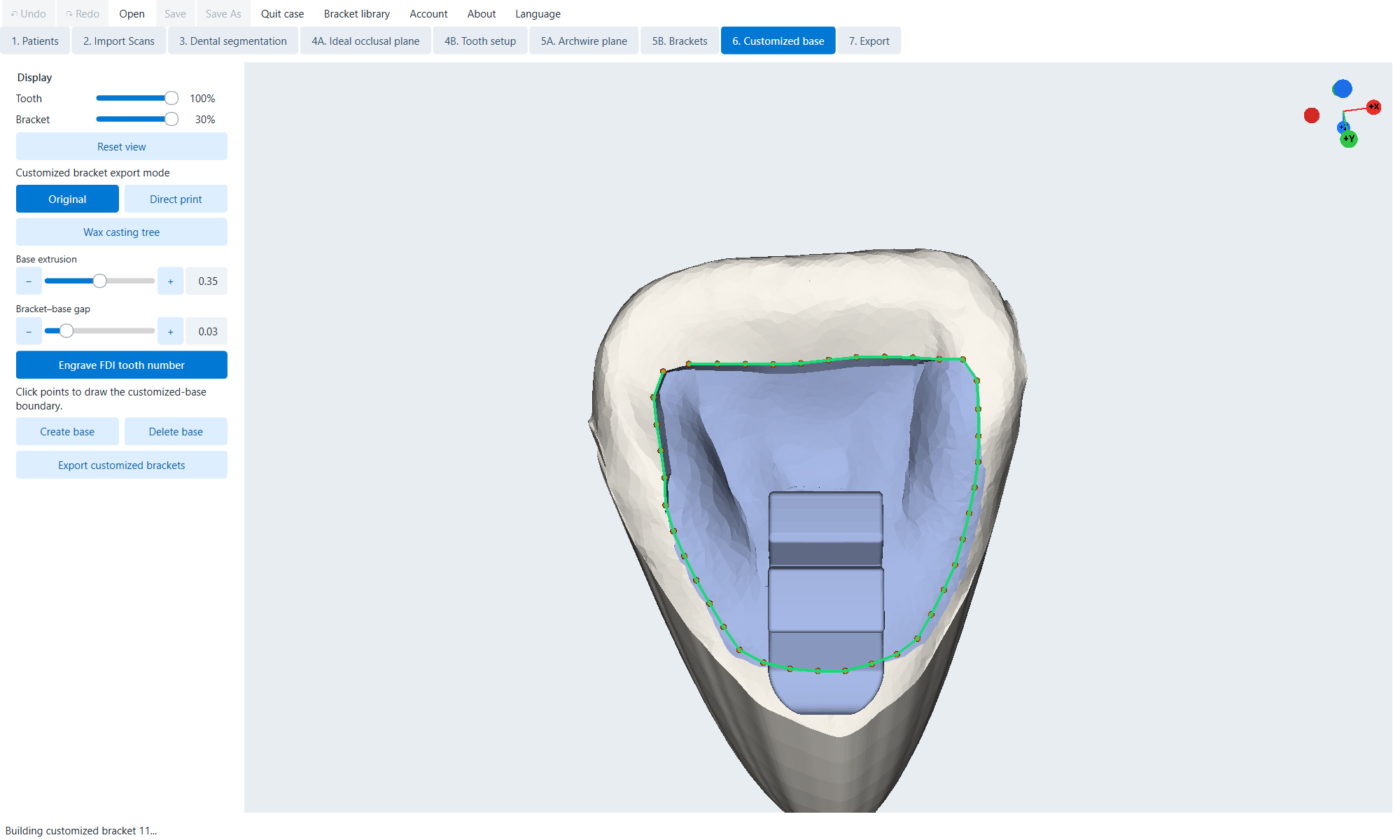
Customized base
Teeth 11; border and base render directly from Sample Patient_0000.

Original — adhesive sole design

OriginalEdit borders and create/delete bases.
Base extrusionBase thickness 0.10–0.60 mm in display control.
Bracket-base gapBody-base gap.
Engrave FDI tooth numberEnable/disable FDI number on manufactured braces.
Click boundary pointsDraw a closed border on the tooth surface.
Create baseCreate base with current boundary/parameters.
Delete baseDelete the selected tooth base.
Customized-base FDI tableSelect the tooth and see if the tooth has geometry.
  1. Choose teeth with accepted bracket positions.
  2. Rotate the surface approximately perpendicularly and draw a clean border around the pad.
  3. Set extrusion/gap, press Create base.
  4. Check margin, adaptation, body-base connection, slot and FDI engraving.

Direct print

Direct printArrange braces for direct printing.
Support diameter / heightSet support diameter and height.
Left-click / Drag / Right-clickAdd, move, or remove support.
Shift when placing/draggingTouching of the patch/slot seal is allowed as an exception.
RaftEnable/disable general raft.
Reset supportsUnedit and rebuild.
Export allExport GLB, 3MF or STL assemblies.
Export separatelyExport STL separately.

Wax casting tree

Wax casting treeArrange into a molded stem tree.
Support heightMounting height of selected braces.
Master sprue diameterMain stem diameter.
Bracket densityDistance/density.
Lowest bracket attachmentLowest mounting height.
Rearrange bracketsRecalculate the layout.
Common tree / Separate treesMerge or split top/bottom trees.
Export customized bracketsExport current tree to STL.
Export separatelyExport separate trees where available.
Use the FDI checkbox to confirm the correct bracket is included in the print/cast.

12. Step 7 — Export

Export
Ideal setup in Model; Individual braces appear around the arch.

Output and location

ModelCreate a print model with the selected bracket type.
TrayCreate an indirectly mounted transfer tray.
JigCreate a jig for each bracket and insert an optional slot.
Original unsegmentedUse the original jaw surface.
Original segmentedUse regenerated teeth/gums.
Ideal setupUse teeth/gum setup.

Formula for braces for each tooth

– No bracketRemoved from output.
O OriginalUse original library braces.
R Raised baseUse braces with lifting bases.
C Customized baseUse individual braces/bases Step 6.

Prepare the model

Cut all / Cut selectedTotal gingivectomy or selective FDI.
Gingiva cutting strengthDepth/intensity of cut.
Restore gingivaDelete the current crop area.
Emboss pt codeEmbossed patient code.
Auto support / Del all supportCreate or remove support.
Support diameterSupport thickness.
Seal bracket slotsClose slot.
Seal wing undercutsFill in the wing undercut.
HollowEnable/disable empty model.
Hollow wall thicknessShell thickness.
Model base heightModel base height.

13. Export Tray, Jig, STL and PDF of arcs

Tray

Minimum tray thicknessMinimum shell thickness.
Tray-tooth clearanceTeeth-tray gap.
Opacity controlsCheck out the tray and anatomy below.
Boundary handles/lassoExternal/internal editing where the workflow provides.
Both arches / Upper / LowerExport tray selection to STL.

Jig

Inner thicknessTongue/tooth depth.
Outer thicknessOuter body thickness.
Jig heightChewing-gum height.
Jig-tooth clearanceJig-tooth gap.
Elephant foot compensationCompensate the flare of the first printed layer on the lower border.
Bracket slot insert sizeInsert size in inches.
Original / Direct printInsert type/source.
Export all / separatelyExport set of GLB/3MF/STL or STL for each tooth.

General production export

Both archesExport two functions with a bow suffix.
Upper / LowerOnly select supply.
Ctrl+EActivate the current export.
Printed wire thicknessWire drawing line thickness.
Export A4 / LetterCreate A4 or US Letter wire PDF.

Check before export

  • Confirm output type, tooth position and arch.
  • Check all FDI status after changing Model/Tray/Jig.
  • Check for holes, loose pieces, holding undercuts, intersecting supports and unwanted lettering.
  • For hollow models, confirm wall thickness and exit/opening path.
  • Open the file in your printing/molding software and run mesh validation.
STL/GLB/3MF must be validated against material, printer, molding process and local requirements.

14. Bracket Library Manager

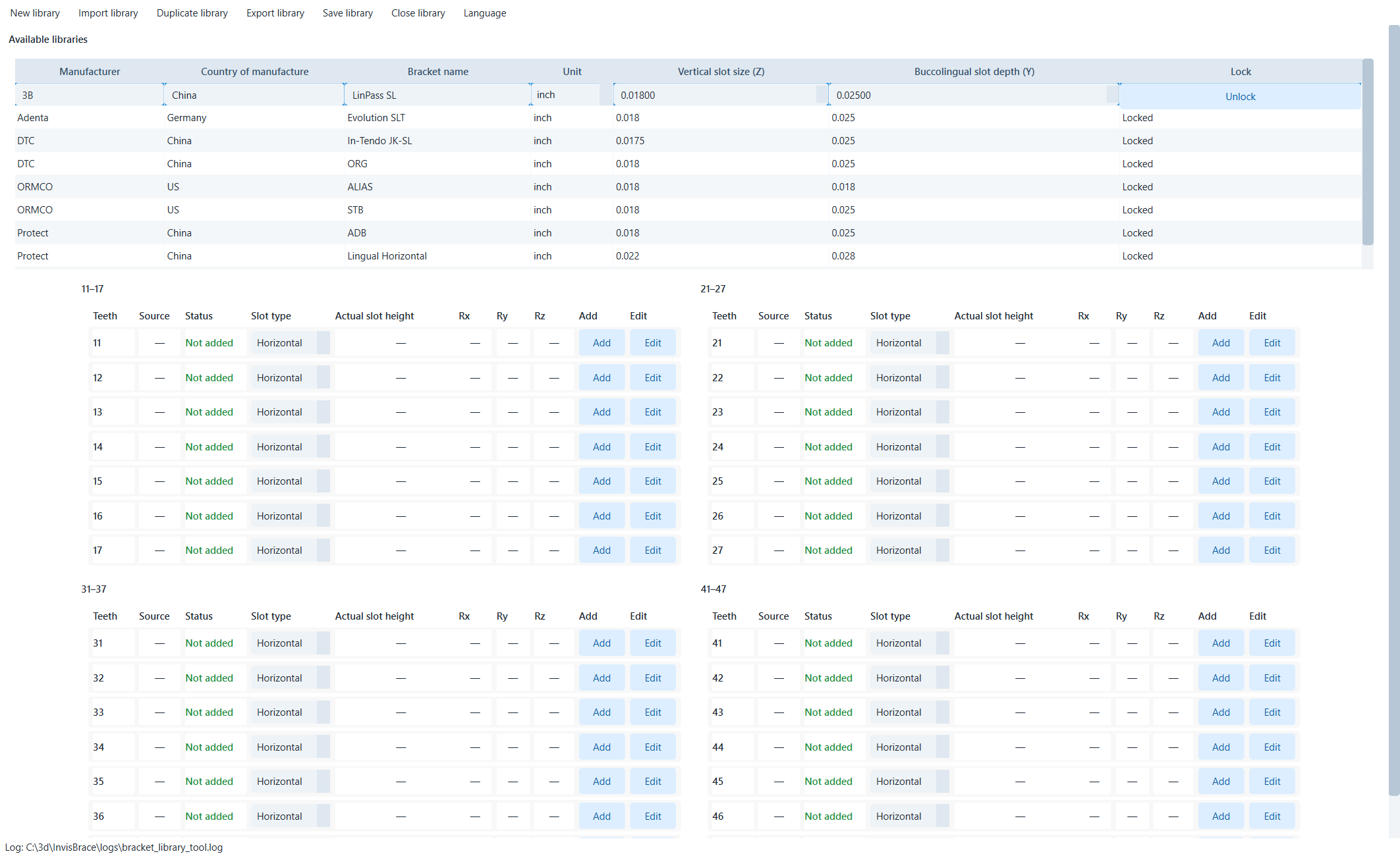
Bracket Library Manager
Library catalog and live tooth matrix.
New library (Ctrl+N)Create a blank draft.
Import library (Ctrl+O)Import ZIP library.
Duplicate library (Ctrl+D)Create editable versions; Read-only built-in library.
Export library (Ctrl+E)Portable ZIP export.
Save library (Ctrl+S)Save changes.
Close library (Ctrl+W)Close; If not saved, it will ask save/discard/cancel.
Manufacturer / Country / NameIdentifier field.
Unitinches or mm.
Vertical slot size (Z)Nominal stand size.
Buccolingual slot depth (Y)Nominal outside-in depth.
Lock / UnlockProtect or allow editing of metadata.
Tooth matrixPower teeth, status, slot type, gauge height, Rx/Ry/Rz and Add/Edit for FDI 11–47.
Slot typeHorizontal/Vertical; Decide on the name of the plane and how to measure it.
Do not edit the built-in library directly; Duplicate then edit and save the copy.

15. Bracket Library Editor

Origin planes
Five three-point anatomical planes define the standard slot system.

Toolbar

Undo / RedoUndo/redo; Ctrl+Z/Ctrl+Y.
Save (Ctrl+S)Validate and save the definition.
CloseClose; Unsaved work will ask save/discard/cancel.

Origin planes

Import bracket meshLoad STL, PLY or OBJ.
Set mesial body planeThree points on the proximal body surface.
Set distal body planeThree points on the far side of the body.
Set occlusal/upper slot-wall planeThree points on the occlusal wall of the slot with the horizontal slot.
Set gingival/lower slot-wall planeThree points on the gingival wall.
Set slot-bottom planeThree points on the bottom of the slot.
Set origin from planesCalculate the slot system and report transform/size.
Confirm originAccept origin, turn on later stage.
The anatomical label describes the bracket, not the screen; Do not interpret upper/lower according to the direction of view.
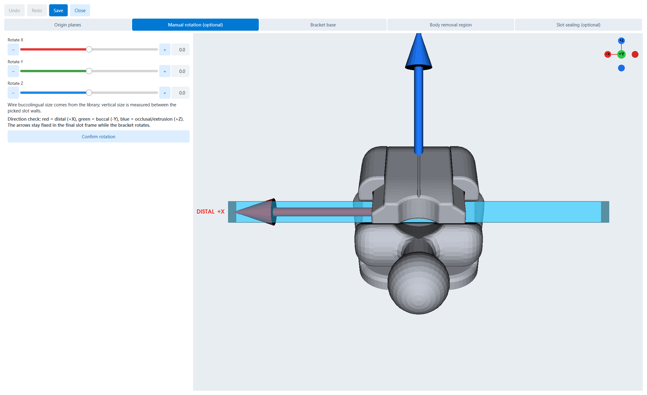
Rotation
Manual rotation with clinical axis indicator.
Rotate XRotate around the far/near axis.
Rotate YRotate around the external-internal axis.
Rotate ZRotate around the chewing/extrusion axis.
Confirm rotationAccept standard direction.
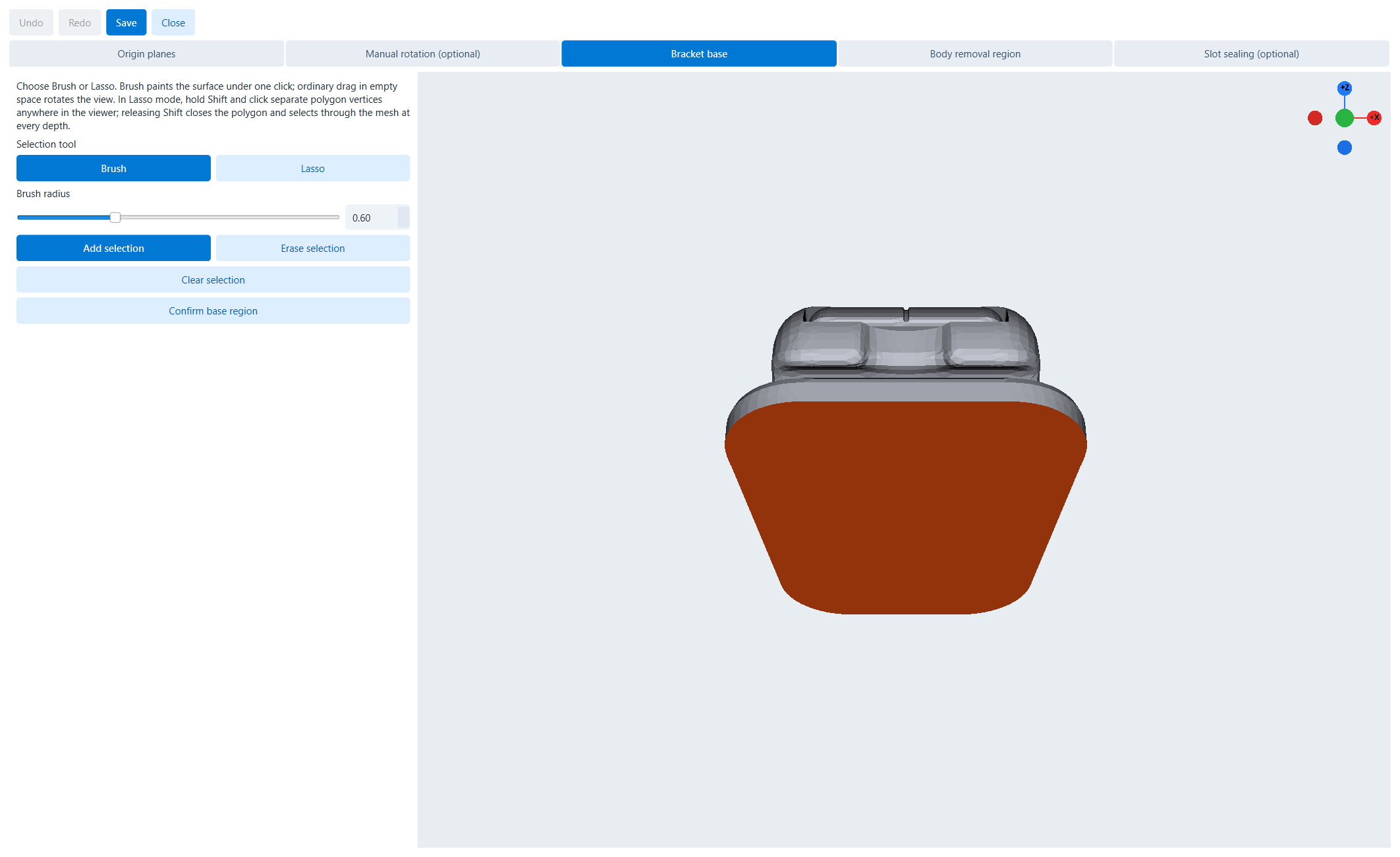
Base
Select brown color for base surface with Brush.
BrushPaint the surface under the cursor; Drag in the empty space to rotate.
LassoHold Shift, click vertex; Release Shift to close and select through the mesh.
Brush radiusBowl radius.
Add / Erase selectionAdd or remove faces.
Clear selectionDelete selection.
Confirm base regionAccept the sole area.
Body removal
Direct or progressive stem type.
Direct selectionRepair the entire type area on the full brace.
Progressive deleteSelect the face, press Delete to add it to the hidden area.
Brush / LassoFill a surface or polygon through the mesh.
Add / Erase / ClearEdit type face set.
Confirm body removal regionAccept and move to sealing slot.
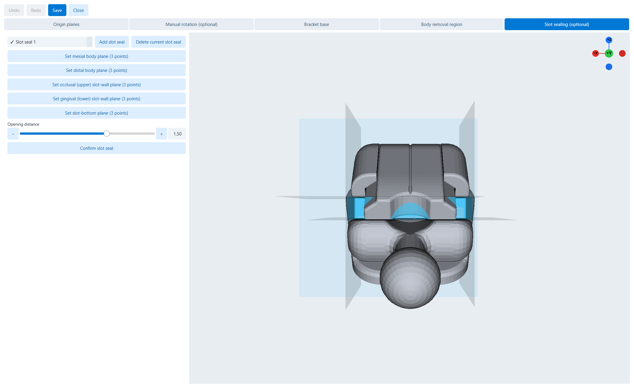
Slot sealing
Optional slot seal with flat face and opening.
Slot seal listSelect seal; Check mark is confirmed.
Add slot sealCreate independent seals.
Delete current slot sealDelete selected seal.
Five plane controlsSelect the near, far, sides and bottom of the slot.
Opening distanceOffset the opening.
Confirm slot sealVerify seals.
Check slot size and axis direction before saving; The error spreads to auto-placement, wires, trays, jigs and individual brackets.

16. Account, credits, language and About

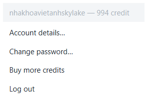
Menus captured directly from the application.

Sign inAccount authentication; Do not include credentials in photos/notes.
Account detailsView identifiers and information.
Change passwordChange password.
Buy creditsOpen credit buying stream.
LogoutEnd of session.
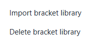
Import bracket libraryInstall ZIP library.
Delete bracket libraryDelete library; Do not delete the ca library in use.
Open Bracket LibraryOpen Manager/Editor in Sections 14–15.
LanguageSelect language; The current item has a check mark.
AboutShow name, version, purpose and application information.
Save the custom library ZIP with the profile before deleting from the workstation.

17. Checklist for quality control from start to finish

PatientSufficient identification/designation; Confirm lost/extracted teeth; correct library.
ScansCorrect file, scale, direction; clean trim; no large holes/islands.
SegmentationEnough teeth, correct ID/axis; two completed arcs.
Ideal planeIn the middle, right direction; no unwanted translation/yaw.
Tooth setupArc, midline, torque/tip/rotation and contact approved.
ArchwireFlat/arc shaped surface is smooth, symmetrical where needed, does not get in the way of teeth.
BracketsYes library; checked slot-wire, clearance, overlap, collision, original/setup.
Custom basesBorder, thickness, gap, engraving, body-base connection and list of approved FDI.
Supports/treesDo not accidentally penetrate the slot/touch the adhesive surface; raft/sprue produced.
Export recipeCorrect Model/Tray/Jig, original/setup and all O/R/C/-.
Output meshSealed/manifold where needed, correct unit, no fragments/collision.
External validationOpened, oriented, supported, slice/test and saved with revision.

Proposal approval minutes

Case / revisionFile name, date/time, revision.
Clinical approverName/signature of physician approving setup and formula.
Manufacturing approverGeometry and process validator.
Output filesName, format, arc, material/process and profile.

18. Troubleshooting

Button is disabledComplete prerequisites, select arch/tooth or wait for geometry worker; see status.
Missing teeth in selectorCheck for Missing/Extraction, wisdom teeth and segmentation.
Mesh upside downUse the translate/rotate function; Resetting the view does not change the mesh.
Trim holds on wrong sideInvert kept side or Undo and redraw.
Segmentation leaks into the gumsUndo, fix the neck point and use Manual.
The shaft causes the teeth to go wrongCheck axes and Tooth local/Ideal plane.
Auto-place clearance is poorCheck wire plane, slot metadata/origin, min distance, axes and wire shape.
Create base is disabledChoose teeth with valid brackets and closed margins.
Support through the restricted areaDrag/delete; Do not hold Shift unless you actively touch it.
Wax layout is tightReduce density, increase attachment height, adjust sprue, Rearrange.
Preview is missingWait to prepare; Avoid changing modes while Tray/Jig/hollow is being created.
Tray/Jig controls are missingConfirm correct output mode.
Do not edit built-in librariesDuplicate and then edit the copy.
Ca opened the wrong bracketInstall the correct library, reopen ZIP, verify identity.
Export error/invalidEdit the mesh, remove support, turn off each seal and try again from the saved revision.
Save As error case before resetting segmentation, changing library or deleting base.

19. Keyboard and mouse quick reference

Ctrl+OOpen ZIP; in Library, import.
Ctrl+SSave ca/definition/library.
Ctrl+Shift+SSave As new ZIP.
Ctrl+NQuit case; in Library, New.
Ctrl+Z / Ctrl+YUndo / Redo.
Ctrl+EExport; in Library, export library.
Ctrl+DDuplicate library.
Ctrl+WClose library.
DeleteCommit the selected face to the progressive removal area.
Shift + lasso clicksAdd vertices; Release Shift to close/select through the mesh.
Shift + support actionLet the support touch the bonding face/slot seal.

Terminology

Arch / FDIArch / two-digit tooth symbol.
Ideal setupFinal arrangement according to plan.
Original segmentedThe base position is equal to the separated tooth/gum surface.
Original unsegmentedOriginal jaw surface before segmentation.
Raised basePad/offset under bracket.
Customized basePatient-specific patch.
Slot sealSlot closure geometry.
Wing undercut sealGeometric filling of wing undercut.
RaftGeneric print base.
Sprue treeThe casting network connects the wax pattern to the main stem.
Elephant footFirst layer flared type; compensation offset bottom edge.

20. Final operational handover

Before moving to production, provide the saved InvisBrace case version, production files, library identifiers, output recipes, material/process assumptions, and approval records. Keep the clinical source ZIP separate from the derived export.

Reconstruction is not just STL. Save with ca ZIP, library ZIP, export settings, output files and approval notes.

↑ Back to top
InvisBrace

InvisBrace User Guide • Complete 20-section PDF content

Enlarged photo